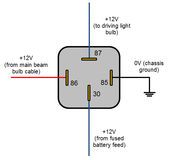
We Have high power relays high capacity standard relays micro relays ISO 280 relays Relay connectors and terminals. 85 - electromagnet coil.
Automotive Relay Guide 12 Volt Planet
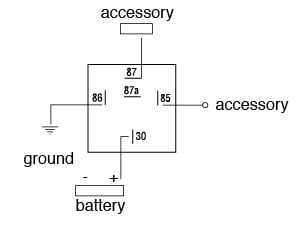
87-Normally open output NO 87a-Normally closed output NC 3.
. Connector - Acceleration Sensor. Normally open or normally closed types. 85-Ground side of the coil.
These relays are so common that they are made everywhere around the world. 1 A for Amperage or Amps. You cant tell but thats 85 on the right and 86 on the bottom.
Sometimes the DIN numbers. Although relays do eventually wear out after repeated use the potential for failure can be reduced if they are replaced periodically or you could wire two relays in parallel. Our standard and customized relays provide critical switching functions in automobiles trucks buses and commercial construction and off-road vehicles.
Below are some examples of basic 12 volt DC. Two 38 Two 14 38 Terminals. The use of the relay beyond its specified characteristics or beyond suf-ficiently tested life expectancy bears the risk of dangerous conditions.
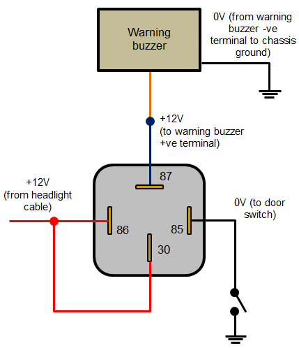
ISO is short for International Standard Organization. 86 - electromagnet coil. In an automotive electrical system it is undesirable to have high current and thick wiring running through the dash panel to the horn switches and the PCM.
Output for a Relay Realizing that 85 and 86 are the coil pins these pins will be transferring the current through the coil. The number used to identify connectors grounds and splices usually indicates where they are located in the vehicle. Most do as this has become standardized numbering based on Boschs interpretation of DIN Standard 72-552 which deals with most electrical wiring.
Connector - Brake Fluid Level Sensor. The terminal numberings found on a relay body are taken from DIN 72552 which is a German automotive industry standard that has been widely adopted and allocates a numeric code to various types of electrical terminals found in vehicles. Instead the vehicles different control modules use a low current signal or ground on thin gauge wiring and a relay to activate the door locks fans idle control.
30-Switch power for the relay. Please help to improve this article by introducing more precise citations. Maxi ISO Automotive Relay Sockets Component Type.
DIN 72552 assigns a numeric code that clearly defines the function of each pin terminal in a relay. All DIN relays should have the terminal numbers on the bottom. Attach the other to relay terminal 85 coil ground.
Relay Connectors Terminals Required. ISO relays are currently used by almost all automotive manufacturers today. List three methods that can be used to help locate a short circuit.
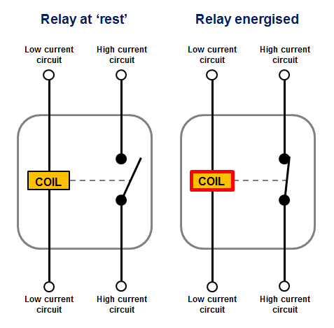
The magnetic flux of the coil distorts the magnetic flux of the permanent magnet to switch the contacts in either position. 85 will be used to ground your relay while 86 will be connected to the switchable power. By using a relay near the item being switched you use less of the heavier gauge wire.
When the relay is off the common and Normally Closed contacts are connected. Normally it is in neutral position the direction of the current flow switches it into either. The user has to prevent such conditions by adequate measures being entirely responsible in case of non-observance.
30 and 40 amp relays are common in automotive use. All switches and relays on a schematic are shown in their normal position either. Both 4 and 5 pin designs are used in both standard mini and micro sizes.
Connector - Accelerator Pedal Sensor. I hope there isnt a test on this. This system was developed in the German automotive industry and has since been adopted across the world as the standard method for labelling and identifying electrical terminals.
RLY-T37510 14 Terminals RLY-T25014 Molding. To the best of my knowledge the Pins on 4 and 5 pin relays are numbered and lettered in a universal way. On mine you can see the labels for terminal 87 at the top and 30 on the left.
The terminals on the outside of a 4 or 5 pin mini relay are marked with numbers as shown below. Polarized relay are made up of electromagnetic coil and a permanent magnet. 2 ORN for wire diameter and color 3 1340 for Circuit Path ID.
70 Amp Relay Connector PR04-WH - 4 Terminals 2-38 2-145 Pack. To test the relay itself take two wires each about a foot long with a female spade terminal at one end and stripped at the other end. The most common type of relay used in automotive applications is the single poledouble throw.
Also known as the Bosch relay the SPDT has a common movable contact that moves between two fixed contacts termed Normally Open and Normally Closed. Our automotive relay types include plug-in relays PCB relays high-current relays and high-voltage relays including automotive contactors. Connector - Air Injection Reactor Pump.
ISO relays were designed to try and standardize relay connections making it easier to test and design systems. Heat Stablized Thermoplastic Operating. Connectors 45 Connector - AC Pressure Transducer.
Touch the 86 wire to the batterys positive post and the 85 wire to the batterys negative post. List and identify the terminals of a typical ISO type relay. Some may argue that relays add an additional failure point to an electrical system.
30 - the common switch connection. May 2015 Learn how and when to remove this template message DIN 72552 is a DIN standard for labeling the electric terminals in automotive wiring. 87 - Normally Open NO Pin.
Most wiring diagrams include the wire color circuit number and wire gauge. All product data are intended for users with knowledge and experience in. 4 and 5 pin designs SPST SPDT are used in both styles of automotive relays.
The most common conventional relay used for automotive applications is the 5-pin 30A40A relay. Unless you want to be replacing these on a regular basis stick to the relays made in the USA Japan or Germany. Identify connectors grounds and splices.
87a - Normally Closed NC Pin. The most common relays used to control electrical accessory devices in the automotive industry are ISO Mini and Micro relays. The most frequently used labels are listed in the table below.
Connector - Barometric Pressure Sensor. Notable deviations from original DIN to Current Ver-6 DIN Bosch Terminal 87 30 Common Relay Contact 87b 87 Normally Closed Contact. Connector - Air Pump.
There are mostly three positions in these relays. Here are a few label examples. And here are another four notations youll find in factory service manuals 4 P for pass through grommet 5 A for Pin ID Location 6 C1 for Terminal Connector ID 7 B for battery positive.
86-Power side of the coil. Although most relays are labeled at the bottom you can always find the 30 pin set perpendicular to pins 87 and 87a for easy identification to the power source. With decades of experience in worldwide support.
Attach one spade connector to relay terminal 86 coil. Connector - ABS Modulator Sensor.
Automotive Relay Diagram
Automotive Relay Guide 12 Volt Planet
Automotive Relay Guide 12 Volt Planet
Automotive Relay Guide 12 Volt Planet


0 Comments